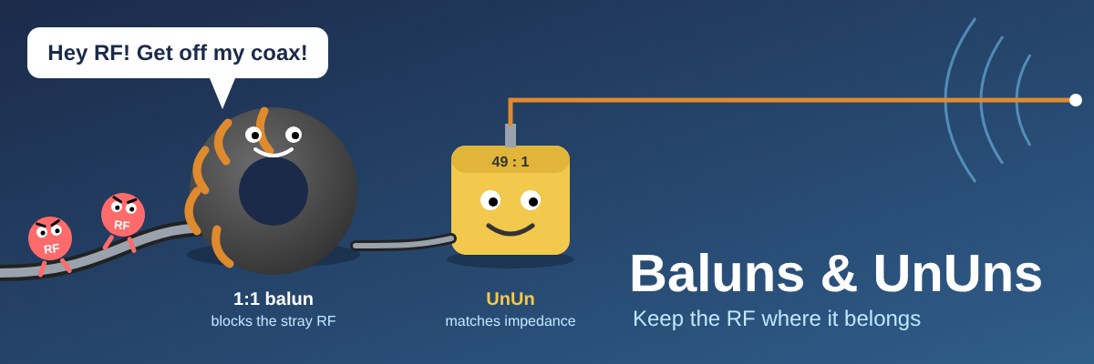
Few parts of an antenna system cause as much confusion as the little box (or the lump of coax and ferrite) at the feedpoint. Balun, UnUn, choke, transformer: the names get used interchangeably and the marketing does not help. This post sorts out what each one actually does, when you need one, and how to avoid the common mistakes.
A note before we start: this is an amateur's guide, written by a hobbyist for other hobbyists. It is not the last word on the subject. Real-world results depend on your antenna, your cable, your ferrite and your surroundings, and experienced builders will sometimes disagree on the details. Treat the figures as starting points, and measure with an analyser where you can.
Balanced vs unbalanced
Coax is an unbalanced line: the centre conductor carries the signal and the braid is held at ground potential, so the two conductors are not symmetrical. A centre-fed dipole is a balanced antenna: both halves are identical and each one should see equal and opposite current.
Connect the two directly and the antenna cannot tell the braid is meant to be ground. Part of the current flows on the outside of the braid as well as the inside. That is common mode current, and it turns your feedline into part of the antenna.
Why common mode current is a problem
A feedline that radiates distorts the antenna pattern, changes the SWR depending on how the cable is routed, and brings RF back into the shack. The usual symptoms are:
- RF feedback on the microphone, or a tingle from the rig case or key
- SWR that changes when you move the coax or touch it
- Interference to TVs, broadband routers and audio gear at home
- Increased local noise on receive, because the braid picks up household interference and carries it into the radio
Figure 1: a dipole fed straight from coax (top) and through a 1:1 current balun (bottom).
Balun vs UnUn
The names describe what is on each side of the device.
- Balun (balanced to unbalanced): coax on one side, a balanced load such as a dipole on the other.
- UnUn (unbalanced to unbalanced): coax on one side, an unbalanced load such as a random wire or end-fed on the other, usually with impedance transformation.
A 1:1 balun mainly stops common mode current and does no impedance transformation. A 4:1 balun or a 9:1 UnUn does both jobs: it steps the impedance and, in the balun case, converts balanced to unbalanced.
Where does a line isolator fit in?
A line isolator (also sold as a choke, common mode choke or feedline choke) is a third device that is easy to confuse with a balun. It sits in the middle of a coax run with coax on both sides. Its only job is to block common mode current on the outside of the braid. It has no balanced side and no impedance ratio.
| Device | What it connects | Changes impedance? | Main job | Typical position |
|---|---|---|---|---|
| Line isolator (choke) | Coax to coax | No | Block common mode current on the braid | At the shack entry, at the rig, or part way along the feedline |
| 1:1 balun | Coax to a balanced antenna | No | Convert balanced to unbalanced and block common mode current | At the antenna feedpoint |
| 4:1 or 6:1 balun | Coax to a balanced, higher-impedance load | Yes | Convert balanced to unbalanced and step the impedance | At the feedpoint, or at the tuner end of open-wire feeder |
| UnUn | Coax to an unbalanced load such as a wire | Yes | Step the impedance of an end-fed or random wire | At the feedpoint |
A 1:1 current balun and a line isolator are often built in exactly the same way, with coax wound on ferrite. The difference is where you put them and what is on the other side. If the other side is a balanced antenna, it is acting as a balun. If it is more coax, it is acting as a line isolator.
The practical lesson is that an UnUn is not a substitute for a choke. It changes the impedance but does not reliably stop common mode current on the coax, which is why the end-fed and random-wire examples later in this post add a choke on the feedline. A good rule of thumb is to use a balun or UnUn to deal with the antenna, and a line isolator to deal with the feedline.
Common ratios and where they are used
| Ratio | Type | Typical use |
|---|---|---|
| 1:1 | Balun (current balun or choke) | Resonant dipoles, inverted vees and yagis fed with 50 ohm coax |
| 4:1 | Balun | Folded dipoles (around 300 ohm, best with 75 ohm coax), some loops and other high-impedance balanced antennas |
| 4:1 or 6:1 | Balun fed with open-wire line | Multiband doublets via an ATU; the balun sits at the tuner end |
| 9:1 | UnUn | Random wires and long wires, typically with a counterpoise |
| 49:1 (or 64:1) | UnUn | End-fed half-wave (EFHW) antennas, which present a few thousand ohms at the feedpoint |
The numbers are impedance ratios, not turns ratios. A 4:1 impedance ratio uses a 2:1 turns ratio, and a 49:1 ratio uses 7:1 turns, because impedance scales with the square of turns.
Where to use them, and why
The right device depends on two things: whether the antenna is balanced or unbalanced, and what impedance it presents at the feedpoint. The table sets out where each one goes and the reason behind the choice.
| Antenna | Use | Where it goes | Why |
|---|---|---|---|
| Resonant dipole or inverted vee | 1:1 current balun | At the feedpoint | The antenna is balanced and its feedpoint impedance (typically 50 to 75 ohm) is already close enough to 50 ohm coax, so no step-up is needed. The balun just stops the braid taking part. |
| Yagi or beam with a balanced match | 1:1 balun or choke | At the feedpoint | Keeps the pattern clean and stops the feedline distorting the front-to-back ratio. |
| Folded dipole | 4:1 balun | At the feedpoint | A folded dipole is around 300 ohm. A 4:1 balun brings that down to something coax can use, and the match is best with 75 ohm coax. |
| Doublet with open-wire feeder | 4:1 or 6:1 balun | At the tuner end, not at the antenna | The open-wire feeder is balanced all the way down, so the balun is only needed where it meets the unbalanced coax or tuner output. |
| End-fed half-wave (EFHW) | 49:1 UnUn plus a choke | UnUn at the feedpoint, choke on the coax | The wire end sits at a few thousand ohms. 49:1 steps roughly 2450 ohm down to 50 ohm. |
| Random or long wire | 9:1 UnUn with a counterpoise | At the feedpoint | Impedance changes from band to band. 9:1 brings a typical value of a few hundred ohms into a range an ATU can handle. |
| VHF/UHF colinear or vertical | Choke (snap-on ferrite stack or sleeve) | At the base of the antenna, then further down the cable | With little or no ground plane the braid becomes part of the antenna, so the SWR and pattern depend on the cable until it is blocked. |
| Any coax entering the shack | Choke (ferrite stack or coax coil) | Where the coax enters the building or reaches the rig | Stops RF travelling inwards on the braid and household noise travelling in, whatever the antenna. |
Example: an end-fed half-wave
An EFHW is the classic UnUn job. The feedpoint is at a voltage maximum, so the impedance is very high and a plain coax connection would give a terrible SWR. The 49:1 UnUn fixes the impedance, but it does not stop the coax radiating, which is why a choke a short way down the feeder is worth adding.
Figure 2: the usual EFHW arrangement.
Example: a random wire
A random wire has no neat resonance, so its impedance wanders as you change band. A 9:1 UnUn pulls the typical value into a range the ATU can cope with, and the ATU does the fine matching. The UnUn needs something to push against: with no counterpoise or earth the coax braid becomes the return path and you are back to common mode current.
Figure 3: a random wire only works well with a proper return path. The 450 ohm figure is a typical working value, not a fixed one.
Voltage baluns and current baluns
A voltage balun forces equal voltages at the two output terminals. A current balun forces equal currents. Real antennas are never perfectly symmetrical, for example when one leg of a dipole is near a mast or a wall, and in that situation the current balun keeps the currents equal so common mode current stays low. This is why a 1:1 current balun (often called a choke balun) is generally the better choice at a dipole feedpoint.
Most good 1:1 designs are Guanella-style transmission line transformers: coax or a bifilar pair wound through a ferrite core so that the common mode path sees a high impedance while the wanted differential signal passes through almost untouched.
Choosing a core
Ferrite mix matters more than most people expect. As a general guide:
| Mix | Good for | Notes |
|---|---|---|
| Type 31 | All-round HF choking, strongest below about 10 MHz (160m to 40m) | High permeability gives more choking impedance on the low bands, and it is close to type 43 above about 10 MHz. The usual first choice for HF chokes |
| Type 43 | Transformer windings, and chokes on the upper HF bands (20m to 10m) | The usual choice for UnUn transformer windings, and a good choke mix on the higher bands |
| Type 61 | Upper HF and VHF | Lower loss at higher frequencies, less choking at the low end |
| Type 77 | Low HF and below | Very high permeability, which is why it is common in broadband and low-frequency work |
Size matters for power. A small core will saturate and heat up long before a large one, and a saturated core stops working as a balun and starts distorting your signal. For 100 W, an FT240-sized core is a comfortable choice; for higher power, stack cores or use a larger one.
The cheap option: a coax choke
You do not always need a purpose-built balun. Coiling the coax a handful of turns near the feedpoint, or threading it through a stack of clip-on ferrites, adds common mode impedance. Both approaches are cheap and can work well if the ferrite mix suits the band, but a coil of coax on its own is narrowband, so the result varies a lot between bands. If you operate on several bands, a wound-on-core balun or a stack of the right mix usually gives more consistent results.
How to make them
All of these are simple builds that need a soldering iron, a ferrite core and some patience. The first three builds cover most of what a ham needs: a 1:1 choke balun, a 49:1 UnUn for an end-fed half-wave, and a 9:1 UnUn for a random wire. The fourth is a short note on 4:1 baluns. Treat the turns counts as starting points and check the result with a NanoVNA before it goes up in the air.
What you need
- Ferrite toroid: an FT240-43 (2.4 inch) is the usual choice for the 49:1 and 9:1 builds, and an FT240-31 is the better choice for the choke (type 43 also works). Buy from a reputable supplier, because fake cores are common. A quick check is to wind 10 turns and measure the inductance with the NanoVNA or an LC meter, then compare it with the datasheet value.
- Wire: 1.5 mm enamelled copper for the transformer windings. PTFE-insulated wire is nicer if you can get it, because it handles heat and high voltage better.
- Coax for the choke: RG316 or RG142 (PTFE jacket) is easy to wind and handles heat well. Thicker cable such as RG58 needs a larger core or a stack of cores. On HF a short tail of thin coax adds almost no loss. Do not do this at VHF and UHF, where thin coax has more loss and a lower power rating (see the colinear section).
- Connectors and box: an SO-239 or N-type chassis socket, stainless terminals or wing nuts for the wire, a weatherproof box, and cable glands.
- Tools: soldering iron, craft knife or fine sandpaper for stripping enamel, heat-shrink, cable ties and a NanoVNA.
Build 1: a 1:1 choke balun
This is the simplest and most useful build. The coax itself is wound through the core, so the wanted signal inside the cable is untouched while the braid exterior sees a high impedance.
- Pass the coax through the centre of the core in a single layer, around 8 to 12 turns for an FT240. Count a turn each time the cable goes through the hole.
- Space the turns evenly around the core and keep the two ends well apart, because turns that touch add capacitance and reduce the choking on the higher bands.
- For a dipole balun, strip each end of the coax and take the centre conductor to one terminal and the braid to the other. For a choke on a feedline, simply fit connectors to each end.
- Keep the braid pigtails as short as you can, and fit strain relief so the winding cannot tug on the solder joints.
- Secure the turns with cable ties or heat-shrink, then mount the whole thing in a weatherproof box.
Figure 4: schematic of the winding. In the real thing the coax is one continuous run through the core.
Build 2: a 49:1 UnUn for an end-fed half-wave
The simplest version is a single winding with a tap, an autotransformer. A turns ratio of 7:1 gives an impedance ratio of 49:1 because impedance scales with the square of turns.
- Wind 14 turns of 1.5 mm enamelled wire on an FT240-43, spaced evenly around the core.
- Make a tap 2 turns up from the end that will be connected to the coax braid (the cold end). Leave a short loop at that point, scrape off the enamel, and solder on a short tap lead.
- Connect the tap to the centre pin of the SO-239.
- Connect the cold end to the SO-239 ground lug and to a terminal for the counterpoise.
- Connect the far end of the winding (the hot end) to the terminal for the radiating wire.
- Many designs add a small compensation capacitor, typically somewhere around 100 to 200 pF in a high-voltage C0G/NP0 type. Its value and position are found by testing on the NanoVNA, so treat it as optional and sweep with and without it.
- Mount everything in a weatherproof box with the wire terminal on the outside and a drip loop on the coax.
Figure 5: the winding is one continuous coil. The tap simply divides it into 2 turns and 12 turns.
Why 2 and 14 turns? The core needs enough inductance on the coax side to look like a high impedance compared with 50 ohm. An FT240-43 gives roughly 1,000 nH per turn squared, so 2 turns is about 4 uH, which is fine from 40m upwards. For 80m the same design scaled up to 3 turns on the coax side and 21 in total (still 7:1) gives more inductance for the lower bands.
Add the choke. Fit a Build 1 choke a short way down the coax, commonly around 0.05 wavelength at your lowest band (about 2 m for 40m and 4 m for 80m). The short length of coax between the UnUn and the choke then acts as a counterpoise, which is why many EFHW designs need no separate counterpoise wire. If the SWR is unstable or you get RF in the shack, add a short counterpoise wire of a few metres as well.
Build 3: a 9:1 UnUn for a random wire
The method is the same as the 49:1 but with a 3:1 turns ratio (which gives 9:1 in impedance). Wind 12 turns on an FT240-43, put the tap 4 turns up from the cold end, and wire it exactly as in Figure 5: tap to the coax centre, cold end to the braid and the counterpoise or earth, hot end to the long wire. This is a scaled version of the 49:1 design rather than a published standard, so check it with the 450 ohm test load before use.
Commercial 9:1 units and many published designs use three twisted wires instead (trifilar), which gives a wider bandwidth. The tapped version is easier to get working and is fine for experiments. If you move to a trifilar design later, copy a published wiring diagram exactly, because a swapped connection gives the wrong ratio.
Build 4: a 4:1 balun
The cleanest homebrew version is a Guanella design: two equal transmission-line sections, each wound on its own core, with their inputs connected in parallel and their outputs in series. Each section ideally runs at about 100 ohm, and twisted pair wire is the usual choice. It is more fiddly than the other builds, so if you are not set on making one, a good bought 4:1 balun is often the sensible option.
Winding tips
- Count turns by the number of passes through the hole, not the number of loops on the outside.
- Scrape the enamel completely at each connection. If the solder will not take on a bare patch, there is still enamel left.
- Keep every lead short, especially the tap and the connections to the sockets, because lead inductance shows up on the upper bands.
- Do not kink the coax and do not wind tight against sharp core edges, which can damage the insulation.
- Run low power first. After 30 seconds of carrier the core should feel cool. Warm means too much loss or too small a core.
Test loads for the NanoVNA
Connect a resistor equal to the design impedance across the output and sweep the bands you care about. Use short leads and non-inductive resistors such as metal film.
| Ratio | Test load | Easy way to make it |
|---|---|---|
| 1:1 | 50 ohm | A 50 ohm dummy load or two 100 ohm resistors in parallel |
| 4:1 | 200 ohm | Two 100 ohm resistors in series |
| 9:1 | 450 ohm | A single 470 ohm resistor is close enough |
| 49:1 | 2450 ohm | A 4.7 kohm and a 5.1 kohm resistor in parallel give about 2450 ohm |
Aim for a flat, low SWR, ideally under 1.5:1 across the bands you will use. A few tenths of ripple at the top end is normal, and a real antenna will not present a perfectly constant impedance anyway, so the bench test is about spotting a badly wrong transformer rather than chasing perfection.
Safety note: the feedpoint of an end-fed half-wave sits at a high voltage. At 100 W into 2450 ohm it is about 500 V RMS, so keep the terminals out of reach, never touch the wire or the UnUn while transmitting, and use a capacitor rated for several kV if you fit one.
Where to put chokes, and how many
One choke is often not enough. Common mode current can be picked up along the whole length of the feedline, so it pays to treat the cable in a few places:
- At the feedpoint: the most important position. This is where the antenna tries to push current onto the braid, so stop it at the source. For a dipole this is the balun.
- Where the coax enters the shack: keeps household noise from travelling along the braid into the rig, and keeps RF from the antenna out of the shack.
- Part way along long runs: on a feedline of tens of metres, add one or two more spaced along the cable so no long stretch of braid is left free to pick up current.
A choke that works well on 20m can do very little on 80m, so match the ferrite mix to the bands you use. A type 31 choke is the best all-rounder across HF. If you also operate on 6m or VHF, add a separate type 43 or 61 choke for those bands.
Chokes for VHF and UHF colinears, and why they keep the SWR steady
Everything so far has been about HF, but the same problem hits VHF and UHF antennas just as hard, and colinears are some of the worst offenders. A colinear is a tall, end-fed vertical, and many of them have no proper ground plane or radials. That leaves the outside of the coax braid as the obvious place for the missing half of the antenna to go.
Why a colinear needs a choke
Without a decoupling choke, part of the current flows down the outside of the braid and the coax becomes part of the radiator. The consequences are the same as on HF, but easier to notice because the wavelengths are short and the cable is long compared with them:
- The SWR depends on the cable. The feedpoint impedance now includes the braid, so changing the cable length or routing changes the SWR you read.
- The pattern is distorted. The radiation from the braid adds to the radiation from the element, which can squash the gain and tilt the beam upwards or downwards instead of putting it along the horizon.
- RF returns to the shack. You can get RF on the rig case, interference to nearby equipment, and extra noise pickup on receive.
Why this keeps the SWR under control
A choke decouples the antenna from the cable. With the braid current blocked, the impedance at the feedpoint is the antenna's own and stops changing with the length or routing of the coax. The SWR you measure becomes stable, repeatable and a true reflection of the antenna, which means you can tune and judge the antenna instead of chasing a number that moves whenever the cable does.
There is a second reason to care about SWR at VHF and UHF. Coax loss is much higher at these frequencies, and loss hides a mismatch: a long run of thin coax can show a pleasant-looking SWR at the rig even when the antenna itself is poorly matched, because the reflected power is eaten by the cable. Measure the SWR at the antenna end where you can, and use low-loss coax on long runs.
A caution: some colinears are designed to use the coax braid as part of their ground plane, so fitting a choke can shift the SWR slightly. If it gets worse after you add one, check the antenna's instructions. It may need its own radials or decoupling sleeve to work properly.
Choke options for VHF and UHF
A sensible target is a choking impedance of a few thousand ohms, around 2 to 3 kohm as a practical aim. Performance matters as well as choking. At VHF and UHF the feedline is already lossy and its power rating is lower than on HF, so it is better not to swap in a thin coax such as RG316 or RG174 just to make a choke easier to wind. The extra loss and the lower power handling will cost more than the choke gains. A typical VHF or UHF feedline is 7 to 10 mm in diameter, and its minimum bend radius makes a wound choke impractical. As an example, our coax choke designer set to LMR400 (10.3 mm) at 145 MHz with the standard bend rule recommends 9 turns on a 196 mm former. That coil is far too large to resonate on 2m and reaches only about 77 ohm. For a few kohm the designer recommends a stack of Fair-Rite tube cores instead. On 2m alone, that is 9 mix 31 cores (about 26 cm long and 495 g) for 2 kohm, or 14 (about 40 cm and 770 g) for 3 kohm. The designer also has a dual-band 2m and 70cm mode and a ferrite mix selector. For 2 kohm on both bands it suggests 10 mix 61 cores (about 29 cm and 550 g), and for 3 kohm a mixed stack of 10 mix 31 and 4 mix 61 cores (about 40 cm and 770 g). Its 70cm figures for mix 31 and 43 are cautious estimates, because the datasheet tables stop at 250 MHz. The practical answer is to leave the cable alone and put the choke around it, using ferrite on the outside of the cable or a sleeve.
| Choke type | Best for | Notes |
|---|---|---|
| Snap-on ferrite stack | The easiest fix on an installed cable, with no change to the feedline. Mix 31 is strongest on 2m, and mix 61 holds up best on 70cm and above | Choose beads with a bore that fits the cable, and for a dual-band antenna mix both types in the stack. One core gives roughly 220 to 280 ohm at 145 MHz depending on the mix, so a few thousand ohms takes about 10 to 15 cores, which is a long, heavy stack on LMR400-size cable. A single bead does very little. Fit it as close to the antenna base as practical, and combine it with a sleeve where you can. |
| Quarter-wave sleeve (bazooka) | Where you need thousands of ohms without a huge stack of ferrite. One sleeve sized for 2m can serve 2m and 70cm together | A conductive sleeve about a quarter wavelength long on the lowest band, joined to the braid at the end away from the antenna, with the open end at the feedpoint (roughly 47 to 49 cm for 2m once the cable jacket is allowed for). Our sleeve designer works out the length for your cable and tube. Because 70cm is three times the frequency of 2m, a 2m sleeve is about three quarters of a wavelength on 70cm and also presents a high impedance there, so one sleeve can serve both bands. Check both bands on the VNA and trim if needed. It does not cover a third band such as 6m, where the ferrites do the work. It sits outside the cable, so it adds no loss and does not limit the power handling. |
| Coiled coax | A weak stopgap at VHF and UHF, more useful lower down | A few turns of the existing cable, with the coil large enough to respect the cable's minimum bend radius (roughly ten times its diameter, so 15 to 20 cm across for 7 to 10 mm cable). The coil only chokes well near its own self-resonance. On 7 to 10 mm cable at the bend limit it is far too large to resonate on 2m, so it adds only around 100 ohm there and is a weak option at VHF and UHF. Measure the effect before relying on it. |
The bazooka balun and other VHF and UHF types
The quarter-wave sleeve above is also known as a bazooka balun, a sleeve balun or a Sperrtopf, and it is the best-known alternative to ferrite at VHF and UHF. A tube is slid over the coax and joined to the braid at the end away from the antenna, leaving the other end open at the feedpoint. The tube and the braid form a short length of coaxial line that is shorted at one end, so a quarter of a wavelength away it looks like a very high impedance. That stops RF travelling down the outside of the braid.
The length is shorter than a free-space quarter wave, because the cable jacket sits in the gap and slows the wave. As examples from our sleeve designer at 145 MHz, a 7.3 mm cable in 15 mm copper pipe needs a sleeve about 47 cm long (velocity factor about 0.91), and LMR400 in 22 mm copper pipe also comes out at about 47 cm. A wider tube leaves a bigger air gap and a slightly longer sleeve. Copper and brass tube can be soldered to the braid. Aluminium is light but cannot be soldered, so it needs a clamp or foil ring and a seal against corrosion. A sleeve is a narrow-band choke, useful over only about 6 percent of the design frequency, so it needs cutting and trimming with an analyser. A sleeve cut for 2m is also at an odd multiple of a quarter wave on 70cm, which is why it suits dual-band colinears. It does nothing useful on bands where its length is a multiple of a half wave.
| Type | What it does | Where it fits | Watch out for |
|---|---|---|---|
| Quarter-wave sleeve (bazooka) | Chokes current on the outside of the braid | Colinears, verticals and other antennas fed with coax | Narrow band, so it needs trimming. Seal the open end against water, and keep it centred on the cable |
| Pawsey stub | A shorted quarter-wave stub across the feedpoint that gives a balanced feed | Balanced antennas such as dipoles and Yagis | Narrow band, and the stub length must allow for the cable's velocity factor |
| Half-wave coax loop (U-balun) | A half-wave loop of coax that gives balanced-to-unbalanced conversion and a 4:1 impedance step | A folded dipole of about 300 ohm fed from 75 ohm coax, or a 200 ohm balanced feed from 50 ohm coax | Narrow band, and it only suits a balanced antenna, not a colinear. The loop length uses the cable's velocity factor |
| Snap-on ferrite stack | Adds loss and impedance to the outside of the braid over a wide band | Any installed cable, and the easiest fix on dual-band antennas | Needs many cores on thick cable, as shown above |
None of these cures a mismatch in the antenna itself. They only stop current on the outside of the coax, so check the SWR and tuning of the antenna first.
Where to put them
- At the base of the antenna: as close to the feedpoint as you can, so the current is blocked where it starts.
- Further down the cable: a second choke a quarter to a half wavelength below the first catches current that couples back onto the braid.
- At the shack entry: keeps any remaining current and household noise out of the rig.
- Cable routing: take the coax away from the antenna sideways for the first metre or so, rather than letting it run straight down alongside the element or the mast, because a cable lying close to the element couples to it strongly.
Figure 6: a typical arrangement for a VHF/UHF colinear. The spacing is not to scale.
How to tell if it is working
- Sweep the antenna with a NanoVNA at the antenna end of the cable, then touch or move the coax. If the SWR changes, common mode current is still flowing.
- Add or remove a short length of cable. On a properly decoupled antenna the SWR should hardly change.
- Compare the SWR with and without the choke across both bands of a dual-band antenna.
- On a handheld, check whether the SWR and signal change depending on where you hold the radio and how the cable lies.
Power and duty cycle
Power rating is not just about peak watts. It also depends on how long you transmit. SSB averages well below peak power because speech is not a constant carrier, while FT8 and other digital modes transmit for most of each slot (an FT8 transmission lasts about 13 seconds of every 15). That is a much harder life for a ferrite core, and a balun that stays cool on SSB can get hot on digital modes at the same power setting.
- Run digital modes at a lower power than the rig's maximum. For a 100 W transceiver, around 25 W is a sensible level.
- Check the core temperature after a few minutes of continuous carrier. Warm is acceptable but hot means you should reduce power or use a larger core or a stack.
- Heat builds up from loss, and loss rises with a poor match. A high SWR at the balun makes the core work harder, so fix the match before you blame the ferrite.
- A hot core loses permeability and saturates more easily, and repeated overheating can crack the core or damage the winding insulation.
Running an amplifier? A checklist
An amplifier does not create problems, but it makes every weakness in a station much louder. Going from 100 W to 1 kW is ten times the power, over three times the voltage, and far more heat in every balun and choke. A setup that was perfectly quiet at 100 W can suddenly have RF in the shack, tripped protection circuits and hot cores. Work through this list before you blame the amp.
- ☐ Check the antenna first. Sweep it with a VNA before applying amplifier power. A high SWR trips the amp's protection and makes every balun and UnUn run hotter.
- ☐ Re-check the core size. A balun built for 100 W is unlikely to be suitable at 1 kW. Use a larger core or a stack, PTFE-insulated wire, and check the temperature after a long transmission at full power.
- ☐ Check the voltage rating at the UnUn. At 1 kW into 2450 ohm an end-fed half-wave feedpoint reaches about 1.6 kV RMS, which is over 2 kV peak. Terminals, capacitors, enclosure spacing and core insulation must all be rated for that. Uncoated ferrite cores are often only rated to around 1,000 V RMS, and many hobby-grade 49:1 units are not built for it.
- ☐ Add chokes in the right places. One at the feedpoint, one at the amplifier output, and one where the coax enters the shack. On long runs add more along the cable.
- ☐ Treat the control cables. Put ferrites on the RF drive lead, the PTT or keying line, the ALC line, band data and CAT or USB cables between the rig and the amplifier. RF on these leads is a common cause of dropouts, odd rig behaviour and PTT problems.
- ☐ Bond the equipment together. Rig, amplifier and tuner should share a short, wide earth strap, and the leads between them should be as short as practical.
- ☐ Check the mains lead. RF can travel along the amplifier's power cable, so a clip-on ferrite or a suitable mains filter can help if you get interference elsewhere in the house.
- ☐ Check the coax and connectors. Make sure the cable and connectors are rated for the higher power on your highest band, and look for signs of heating or discolouration.
- ☐ Step the power up slowly. Start at low power with the amplifier in standby, then raise it in stages, feeling the cores and listening for RF in the audio at each step.
- ☐ Stay clear of the antenna. At higher power an RF burn from a feedpoint or wire is a real risk, so keep the antenna and UnUn out of reach whenever you transmit.
If the problem appears at low power as well, the amplifier is not the cause. Fix the chokes and the antenna first, then bring the amplifier back in.
Common mistakes
- Using a 4:1 balun on a 50 ohm dipole. The impedance is already close to a match, so you simply add a mismatch and extra loss.
- Expecting a 9:1 UnUn to cure a random wire on its own. It matches the impedance but a random wire still needs a decent counterpoise, or the coax braid becomes the counterpoise.
- Using a tiny core at high power. Heat is the giveaway, and a hot core is a core losing power.
- Assuming a bigger balun is always better. Extra turns add self-capacitance and can hurt performance on the upper bands.
- Skipping the choke on an EFHW. The coax often ends up acting as the other half of the antenna, so a choke a short way down the feedline is worth adding.
- Trusting the sticker. Many cheap baluns are undocumented, so measure them rather than assuming the label is true.
Quick decision guide
- Resonant dipole or inverted vee on coax: 1:1 current balun.
- Folded dipole or other high-impedance balanced antenna: 4:1 balun.
- Random wire with a good counterpoise: 9:1 UnUn.
- End-fed half-wave: 49:1 UnUn, plus a choke on the coax.
- Doublet with open-wire feeder: balun at the tuner end, and keep the feeder as symmetrical as you can.
Troubleshooting guide
| Symptom | Likely cause | What to try |
|---|---|---|
| RF in the mic, or a tingle from the rig case or key | Common mode current on the coax | Add a choke at the rig end and at the feedpoint, and keep leads short |
| SWR changes when you touch or move the coax | The braid is radiating | Fit a choke or balun at the feedpoint |
| High SWR on every band with an EFHW | Wrong or faulty UnUn, or no counterpoise | Test the UnUn with a 2450 ohm resistor, then add a counterpoise and a choke |
| SWR on a VHF or UHF colinear changes with the cable length or routing | The braid is acting as part of the antenna | Fit a choke at the base of the antenna and another further down the cable, and route the coax away sideways |
| Core gets hot | Core too small, too much power or duty cycle, or a poor match | Reduce power, use a larger core or a stack, and check the SWR |
| High receive noise that changes when you move or handle the coax | The braid is picking up household noise and carrying it into the rig | Fit a choke at the shack entry and compare the noise level. Also check ferrites on power supplies and USB leads, and try running the rig from a battery to rule out the mains |
| Good SWR on the low bands but poor on the upper bands | Stray capacitance from too many turns, bunched turns or long leads | Use fewer turns, space them evenly and shorten the leads |
| Fine at low power but fails at high power | Core saturation, or arcing at the high-voltage terminals | Use a larger core, check the capacitor's voltage rating, and keep terminals well spaced |
| Interference to a TV, router or audio gear at home | RF on the feedline or on the equipment's own cables | Add a choke at the shack entry, and put ferrites on the affected equipment's cables |
Frequently asked questions
Do I need a balun on a dipole? It is strongly recommended. A dipole will work without one, but the coax is then likely to carry common mode current, which distorts the pattern and brings RF into the shack.
Can I use a 4:1 balun to match a 50 ohm antenna? No. If the antenna is already close to 50 ohm, a 4:1 balun adds a mismatch and extra loss. Use a 1:1 balun instead.
Is a bigger core always better? Not necessarily. A bigger core handles more power, but the extra turns and size can add stray capacitance and hurt the upper bands. Choose the core size for your power and the mix for your bands.
Can I use the same UnUn for an EFHW and a random wire? No. An EFHW needs a 49:1 ratio and a random wire usually needs 9:1. Using the wrong one gives a poor match and wasted power.
Does an UnUn stop common mode current? Not reliably. It changes the impedance, but you should still add a choke on the coax.
Related: if you are building antennas to use with these, take a look at the homebrew antennas section for calculators and build guides.
The short version: a balun is about keeping RF off the outside of your coax, and an UnUn is about matching an unbalanced load to 50 ohms. Pick the one that matches your antenna, size the core for your power, and measure before you trust it.
As said at the top, this is an amateur's guide and not the final word. If something here doesn't match your own experience, or you have a better way of doing it, we'd like to hear about it.