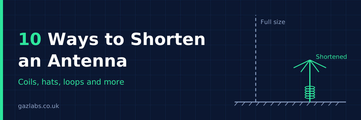
A full-size half-wave dipole on 80m is about 40 metres end to end. Most of us don't have a 40 metre garden, and even on 20m you can run out of room on a balcony, a loft or a campsite. The good news is that an antenna doesn't have to be physically full length to work. It has to be electrically full length, and there are plenty of ways to cheat.
Here are ten ways to shorten an antenna, roughly in the order I'd try them. One honest warning first: every one of these costs you something. Usually it's efficiency or bandwidth, sometimes both. A short antenna that's on the air beats a perfect one that never got built, but go in with your eyes open.
1. Base loading coil
Put a coil at the bottom of a vertical. The inductance cancels the capacitive reactance of the short radiator, so the antenna looks resonant even though it's physically short. It's the easiest method, it's easy to tune, and it's how most mobile whips work. The downside is that current is highest at the base, where the coil is, so the radiating part of the antenna isn't doing much of the work. Efficiency is the price.
2. Centre loading coil
Move the coil up to the middle of the element. Now more of the antenna carries useful current above and below the coil, so it radiates better than a base-loaded version of the same length. The coil needs a bit more care because it sits mid-air and has to cope with wind and weight, but it's the classic compromise for shortened dipoles and verticals.
3. Top loading
Put the coil near the tip. This gives the best radiation of the three coil positions, because current stays high along most of the antenna. The catch is that it needs a bigger coil for the same shortening, and the weight sits at the worst place for mechanical stability.
4. Capacity hat (top hat)
Add a set of wires or a disc at the top of a vertical. This adds capacitance at the tip, which makes the antenna behave as if it were longer, and it improves the current distribution along the radiator. Combine it with a coil and you get a surprisingly effective short vertical. A few spokes of wire pointing outward are enough, and they can droop down if you're short of height.
5. Droop the ends or use an inverted-V
The cheapest shortening trick there is. Instead of a flat dipole, hang the centre from a mast and let the legs slope down. The span shrinks, you only need one support, and the impedance drops close to 50 ohms, which is handy. You lose a little gain and the pattern becomes less directional, but for most people it's a good trade.
6. Linear loading (fold the ends back)
Instead of a coil, run the wire out, then fold it back on itself, either along the same line or hanging back down. No coil means no coil losses, and it's very easy to build from wire and spacers. It does take a bit of trimming to get right, and the folded sections slightly reduce the effective radiating length, but it's a great option when you can't hide a coil.
7. Meander or zigzag the wire
Take a long element and bend it into a zigzag so the same wire length fits into a much smaller space. This is how a lot of compact antennas on circuit boards and in portable gear are made. The closer the bends, the more the fields cancel and the lower the efficiency, so keep the spacing generous if you can.
8. Helical winding
Wind the radiator into a spiral around a former. This is the rubber duck on your handheld: a full quarter-wave of wire squeezed into a few inches. It's compact and tough, and it keeps the loading spread along the whole length. Bandwidth is narrow and gain is below a full-size antenna, but it's very hard to beat for portable use.
9. Trap or multiband dipole
Traps are tuned LC circuits placed in the element. On the higher band they isolate the outer wire so the antenna is short and resonant. On the lower band they act as loading coils and let the whole length work. One antenna, two bands, and on the lower band it's shorter than a full-size dipole would be. You pay with some loss in the traps and narrower bandwidth, but one wire for two bands is a nice saving of space.
10. Go small with a magnetic loop
If you really can't fit a wire antenna, a small loop of tube or coax with a variable capacitor can be a fraction of a wavelength across and still work. It's very quiet on receive, handy for apartments, and it rejects a lot of local noise. The catch is that the bandwidth is extremely narrow, so you retune every time you move a few kilohertz, and the capacitor has to handle high voltages when you transmit. Build it carefully.
Quick comparison
| Method | Typical shortening | Main trade-off |
|---|---|---|
| Base loading coil | Large | Lowest efficiency of the coil options |
| Centre loading coil | Large | Coil must be supported mid-air |
| Top loading | Moderate | Bigger coil, weight at the tip |
| Capacity hat | Moderate | Needs some wire or a disc at the top |
| Inverted-V / drooped ends | Small to moderate | Slight loss of gain |
| Linear loading | Moderate | Fiddly to trim |
| Meander | Large | Efficiency drops as bends tighten |
| Helical winding | Very large | Narrow bandwidth, lower gain |
| Trap dipole | Moderate on the lower band | Trap losses, narrower bandwidth |
| Small magnetic loop | Very large | Very narrow, needs constant retuning |
Showing the maths (the easy version)
Every number in this section comes from one example, so you can follow it from start to finish. The example is a vertical antenna for the 40m band with only a 2.5 metre whip to work with. We'll use 7.1 MHz as the frequency, which is the bottom of the busy phone part of the band. If you want a different frequency, swap it in at the start and redo the sums. All you need is a calculator with the usual buttons (×, ÷, √, tan and ln).
Step 1: Find the wavelength
Our frequency is 7.1 MHz. Divide 300 by the frequency in MHz.
300 ÷ 7.1 = 42.3 metres
Step 2: Find the full-size length
A dipole is half a wavelength long, but the wire has to be cut about 5% shorter than that in practice (an effect called end effect). That's where the 143 comes from: 300 ÷ 2 = 150, then 150 × 0.95 = 142.5, which rounds to 143. A vertical is only a quarter of a wavelength, which is half the length of a dipole, so its number is half of 143: 143 ÷ 2 = 71.5. Divide each by the frequency. Our frequency is still 7.1 MHz.
Dipole: 143 ÷ 7.1 (frequency) = 20.1 metres
Vertical: 71.5 ÷ 7.1 (frequency) = 10.1 metres
Step 3: How much shorter is our whip?
Our whip is 2.5 m and the full-size vertical from Step 2 is 10.1 m. Divide the whip by the full-size vertical, then take that away from 1.
2.5 (whip) ÷ 10.1 (full-size vertical) = 0.25
1 − 0.25 = 0.75, which is 75% shorter
Step 4: How "out of tune" is the whip?
A whip that's too short behaves like a small capacitor, and the coil's job is to cancel it. To size the coil we first need to know how big that effect is, in ohms. It takes three small calculations.
a) How thick the whip is, as the radio sees it. Use the whip length (2.5 m) and its radius (a 10 mm tube has a radius of 5 mm, which is 0.005 m).
2 × 2.5 ÷ 0.005 = 1000
ln(1000) = 6.9 (use the ln button)
6.9 − 1 = 5.9
5.9 × 60 = 354
b) How much of a wavelength the whip is, as an angle.
360 × 2.5 (whip) ÷ 42.3 (wavelength from Step 1) = 21.3 degrees
c) Put them together. Find tan of the angle (use the tan button).
tan(21.3) = 0.39
354 ÷ 0.39 = 908 ohms
So the whip is 908 ohms out of tune, and the coil has to be 908 ohms the other way.
Step 5: How big a coil is that?
Coil sizes are measured in microhenries (µH). Divide the 908 ohms from Step 4 by 6.28 times the frequency in MHz (still 7.1 MHz).
6.28 × 7.1 (frequency) = 44.6
908 ÷ 44.6 = 20.4 µH
Step 6: How many turns is 20.4 µH?
Pick a former (the tube you wind the wire on). We'll use a 50 mm diameter tube with a 100 mm long winding. The formula wants inches, so that's 1.97 inches across and 3.94 inches long.
18 × 1.97 = 35.5
40 × 3.94 = 157.6
35.5 + 157.6 = 193.1
193.1 × 20.4 = 3939
1.97 × 1.97 = 3.88
3939 ÷ 3.88 = 1015
√1015 = 31.9, so 32 turns
Spread over 100 mm, 32 turns sit about 3 mm apart, which suits 1.3 mm (16 AWG) wire nicely. Wind a few turns extra, then take turns off while watching the SWR meter.
Step 7: How much power gets wasted?
Your power can go two ways. Some leaves as radio waves, and the rest warms up the coil. We can put a number on each as a resistance in ohms.
a) The part that radiates. Divide the whip length by the wavelength, square it, then multiply by 395.
2.5 (whip) ÷ 42.3 (wavelength from Step 1) = 0.059
0.059 × 0.059 = 0.0035
0.0035 × 395 = 1.4 ohms
b) The part wasted in the coil. Divide the 908 ohms by the coil's quality score, which is called Q. A well-made hand-wound air coil is about 200.
908 ÷ 200 = 4.5 ohms
c) Share it out.
1.4 + 4.5 = 5.9
1.4 ÷ 5.9 = 0.24, which is 24% of your power radiated, and the rest is heat.
In decibels: 10 × log(0.24) = about −6 dB (use the log button), which is roughly one S-point on the other station's meter. That's before ground losses, which make it a little worse. It's why a good coil and good radials matter so much on a short vertical.
Step 8: How much narrower is an inverted-V?
Take the dipole length from Step 2 (20.1 m at 7.1 MHz) and multiply by 0.7 if the legs make a right angle at the top, or by 0.87 if they make a wider angle of 120 degrees.
20.1 × 0.7 = 14.1 metres across with a sharp V
20.1 × 0.87 = 17.5 metres across with a gentle V
Drooping the ends pulls the resonance down a little, so cut each leg slightly long and trim. Half of 20.1 m is 10.05 m, so we'll start at 10.2 metres per leg.
Starting points to build from
Here are starting numbers for every method, all for the same 40m example at 7.1 MHz so they match the sums above. Where a figure is a rule of thumb rather than a calculation, I've said so. Wire sizes are in millimetres first, with the nearest AWG in brackets.
Coils
Turns for each coil come from the same Step 6 sums, using the same 50 mm former and 100 mm winding. Space the turns evenly, with a gap a little wider than the wire. Tight turns lose more power.
| Method | Coil size | Turns | Former diameter | Winding length | Wire |
|---|---|---|---|---|---|
| 1. Base loading coil | 20.4 µH (Step 5) | 32 | 50 mm | 100 mm | 1.3 mm (16 AWG) copper |
| 2. Centre loading coil | about 30 µH (rule of thumb: 1.5 × the base coil) | 39 | 50 mm | 100 mm | 1.3 mm (16 AWG) copper |
| 3. Top loading coil | about 40 µH (rule of thumb: 2 × the base coil) | 45 | 50 mm | 100 mm | 1.0 mm (18 AWG) copper, to keep the weight down |
| 4. Capacity hat, small coil | about 10 µH (rule of thumb: half the base coil) | 22 | 50 mm | 100 mm | 1.3 mm (16 AWG) copper |
The centre and top coils need more inductance because they sit higher up, where there's less whip below them to help. The hat takes over some of the job, so its coil can be smaller. Check all three with your analyser.
Helical winding
A helical antenna is wound from roughly a full quarter-wave of wire, about 10.1 m (Step 2), spiralled up the 2.5 m whip. Use a 25 mm tube, which has a circumference of 3.14 × 25 = 78.5 mm.
10,100 ÷ 78.5 = about 130 turns, spread over the 2.5 m, so about 19 mm between turns. Use 1.0 mm (18 AWG) enamelled copper wire. Start with about 10.2 m of wire and trim. This is the weakest method on efficiency (2/10 in the ratings below), so I'd only use it where size matters more than signal.
Trap dipole for 40 and 20m
The second band is 20m, and we'll use 14.15 MHz for it. A trap is a coil and a capacitor that block the 20m signal, so it has to be tuned to 14.15 MHz.
Pick a coil of 3 µH, which is a handy size to wind. Then work out the capacitor: multiply the frequency by itself, multiply by the coil size, and divide 25,330 by the answer.
14.15 × 14.15 = 200
200 × 3 = 600
25,330 ÷ 600 = 42 pF
Turns for the 3 µH coil, on a 25 mm former with a 25 mm winding (0.98 inch each way):
18 × 0.98 = 17.7
40 × 0.98 = 39.4
17.7 + 39.4 = 57.1
57.1 × 3 = 171
0.98 × 0.98 = 0.96
171 ÷ 0.96 = 178
√178 = 13.3, so 13 turns of 1.0 mm (18 AWG) wire.
For the wire lengths: a 20m half-wave is 143 ÷ 14.15 = 10.1 m, so each side is half of that, about 5 m. Start with 4.9 m from the centre to the trap and 2.8 m beyond it. The 2.8 m is a starting guess that you'll trim for 7.1 MHz. Use 1.6 mm (14 AWG) copper wire.
The methods without a coil
| Method | Starting dimensions | Wire |
|---|---|---|
| 4. Capacity hat | 4 spokes of 1 m each, sloping down from the top of the whip. This is a size that is easy to hang, not a calculated one | 1.6 mm (14 AWG) copper or aluminium |
| 5. Inverted-V | 10.2 m per leg (Step 8), 90 to 120 degrees at the top | 1.6 to 2 mm (14 to 12 AWG) stranded copper |
| 6. Linear loading | 10.2 m of wire per leg. Go out 7.7 m, then fold the last 2.5 m back, held 100 to 150 mm from the first part. Span: 2 × 7.7 = 15.4 m | 1.6 mm (14 AWG) copper |
| 7. Meander | 10.2 m of wire per leg, zigzagged into 9 runs of 1 m with 150 mm between runs (9 × 1 + 8 × 0.15 = 10.2 m) | 1.3 mm (16 AWG) copper |
| 10. Small magnetic loop | 2 m diameter loop, about 87 pF variable capacitor, coupling loop 400 mm across (see below) | 22 mm copper pipe |
Magnetic loop capacitor
A loop is a coil with one turn, so the same idea applies: work out its inductance, then the capacitor that tunes it. For a 2 m loop (radius 1 m) made from 22 mm pipe (radius 0.011 m):
8 × 1 ÷ 0.011 = 727
ln(727) = 6.59
6.59 − 2 = 4.59
1.257 × 1 × 4.59 = 5.77 µH
Then the capacitor, using the same sum as for the trap:
7.1 × 7.1 = 50.4
50.4 × 5.77 = 291
25,330 ÷ 291 = 87 pF
The coupling loop that connects your coax is about a fifth of the main loop's width, so 2 m ÷ 5 = 400 mm.
Three tips. Use the thickest wire that's practical, because thin wire wastes power as heat. Keep coils well away from metal poles and walls. And remember these are starting points, so always trim against an SWR meter or analyser.
Efficiency ratings
Here's how the ten methods compare on efficiency, meaning how much of your transmitter power actually leaves as radio waves instead of turning into heat. These are ballpark figures for a sensible build on the HF bands, compared with a full-size antenna on the same band. The more you shorten, the lower you go in the range, and a poor coil or poor ground will push you below it.
| Method | Typical efficiency | Approx. loss | Rating |
|---|---|---|---|
| 1. Base loading coil | 15 to 30% | -8 to -5 dB | 3/10 |
| 2. Centre loading coil | 25 to 45% | -6 to -3.5 dB | 5/10 |
| 3. Top loading | 35 to 55% | -4.5 to -2.5 dB | 6/10 |
| 4. Capacity hat | 50 to 80% | -3 to -1 dB | 8/10 |
| 5. Inverted-V / drooped ends | 85 to 95% | -0.7 to -0.2 dB | 10/10 |
| 6. Linear loading | 70 to 90% | -1.5 to -0.5 dB | 8/10 |
| 7. Meander | 30 to 70% | -5 to -1.5 dB | 5/10 |
| 8. Helical winding | 10 to 30% | -10 to -5 dB | 2/10 |
| 9. Trap dipole | 70 to 90% | -1.5 to -0.5 dB | 8/10 |
| 10. Small magnetic loop | 20 to 80% | -7 to -1 dB | 6/10 |
A few things to keep in mind. The inverted-V scores top marks because it barely shortens the antenna at all, so it's cheating a bit. The capacity hat, linear loading and trap dipole are the best choices if you want a really shorter antenna without a big loss. The magnetic loop has the widest range because it depends so much on the band and the conductor: on 20m and up, a loop made from thick tube can be excellent, while on 40m and below the same size of loop gets poor quickly. And remember that 3 dB is half your power, so even a loss of 6 dB doesn't mean you can't make contacts, it just means you need to pick your moments.
Bang for buck
Efficiency only tells half the story. A method that shortens the antenna a lot but wastes most of your power isn't necessarily a good deal, and neither is one that costs a lot or takes a weekend to tune. So here's a simple score that puts shortening, efficiency, cost and effort side by side.
Each method gets four marks out of 10, and the bang for buck score is the average of the four (add them up and divide by 4).
Shortening mark: the middle of the typical shortening range, divided by 10 and rounded. A method that shortens by about 50% scores 5.
Efficiency mark: the same rating as in the efficiency table above.
Cost mark: 10 is very cheap (a bit of wire), 1 is expensive (special parts).
Ease mark: 10 is simple to build and tune, 1 is fiddly.
Worked example, the inverted-V: shortening 2 (it averages about 21%), efficiency 10, cost 10 (just wire), ease 9. Total 2 + 10 + 10 + 9 = 31, and 31 ÷ 4 = 7.8.
| Method | Typical shortening | Efficiency kept | Shortening mark | Efficiency mark | Cost mark | Ease mark | Bang for buck |
|---|---|---|---|---|---|---|---|
| 1. Base loading coil | 50 to 80% | 15 to 30% | 7/10 | 3/10 | 8/10 | 8/10 | 6.5/10 (26 ÷ 4) |
| 2. Centre loading coil | 40 to 70% | 25 to 45% | 6/10 | 5/10 | 7/10 | 6/10 | 6.0/10 (24 ÷ 4) |
| 3. Top loading | 30 to 60% | 35 to 55% | 5/10 | 6/10 | 6/10 | 5/10 | 5.5/10 (22 ÷ 4) |
| 4. Capacity hat (with small coil) | 20 to 50% | 50 to 80% | 4/10 | 8/10 | 7/10 | 7/10 | 6.5/10 (26 ÷ 4) |
| 5. Inverted-V | 13 to 30% | 85 to 95% | 2/10 | 10/10 | 10/10 | 9/10 | 7.8/10 (31 ÷ 4) |
| 6. Linear loading | 20 to 30% | 70 to 90% | 3/10 | 8/10 | 9/10 | 6/10 | 6.5/10 (26 ÷ 4) |
| 7. Meander | 40 to 60% | 30 to 70% | 5/10 | 5/10 | 7/10 | 5/10 | 5.5/10 (22 ÷ 4) |
| 8. Helical winding | 60 to 85% | 10 to 30% | 7/10 | 2/10 | 7/10 | 4/10 | 5.0/10 (20 ÷ 4) |
| 9. Trap dipole (lower band) | 15 to 25% | 70 to 90% | 2/10 | 8/10 | 5/10 | 4/10 | 4.8/10 (19 ÷ 4) |
| 10. Small magnetic loop | 85 to 95% | 20 to 80% | 9/10 | 6/10 | 3/10 | 4/10 | 5.5/10 (22 ÷ 4) |
The shortening ranges are typical figures, and the cost and ease marks are my own judgement, so change them to suit your own workshop and budget. The ranking is worth a few notes. The inverted-V wins because it's so cheap and easy, even though it only shortens a little. If you need a big saving in space, the base loading coil, capacity hat and linear loading tie for the best all-round deals, and the magnetic loop gives the biggest shortening of all, at the cost of money and patience. The helical and the trap dipole score lowest, but the trap dipole's real prize is covering two bands with one wire, which this score doesn't count.
Which one should you pick?
If you just need a bit less span, start with the inverted-V. If you've got height but not width, a vertical with a capacity hat is very hard to beat. For portable and handheld use, helical is the one. For a flat or apartment on a tight budget, a small loop is worth the hassle of retuning. And whichever you choose, keep the coil and the radiator as far from metal and walls as you can, because nearby objects pull the tuning all over the place.
Remember that shortening always shifts the resonant frequency, so tune with an antenna analyser or SWR meter and trim a little at a time. Cutting is easy, adding back is not. If you want to work out the numbers before you pick up the wire cutters, have a go with the calculators in our homebrew antennas section.